
Some Background
Fish swim using a combination of active and passive movement. Muscles drive the movement in active swimming while passive motion results from fluidic forces on the body. An established model for researching fish locomotion uses a plastic foil (driven at the leading edge by a motor) to mimic undulatory motion. This simple model has led to tremendous progress in investigating the effects of key variables on swimming. However, the results apply solely to passive motion as the foil is not self-actuating. The passive foil is sometimes too simple and the results do not always agree with live fish swimming data. An active model is needed to fill the gaps in previous research and to advance the field.
Fish-like ‘hard’ robotic systems with gears and motors are active but complicated, and can be difficult to maintain or alter. This hinders exploring fundamental questions. Soft robotic pneumatic actuators (“pneunets”) are simple silicone rubber constructs that are inflated to produce motion.
A team operating out of the Wyss Institute and the Lauder Lab at Harvard University developed a novel, active platform using pneunets. Because “apparatus” is such a dreary and general term, I began calling the apparatus a “pneufish”. This pneufish is capable of producing positive thrust and undulatory motion.
The post-doc leading the project, Ardian Jususfi, has since taken a lecturing position in Sydney, Australia, and I have inherited this project, for a lack of a better description.
How does this thing work?
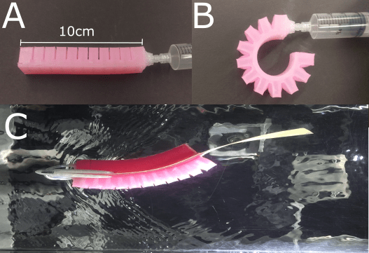
Panel A shows an uninflated pneunet. Each pneunet is made of 10 hollow chambers connected by a hollow channel on the flat side. When air is pumped into the pneunet, the chambers inflate and each chamber pushes against its neighbor(s). Because the chambers are located on only one side, this produces a net curvature, which you can see in Panel B. By sticking two of these on opposite sides of a flexible foil and alternating their activation (Panel C), we can produce undulatory motion.
In the image below, you can see the general construction of each pneufish. The two pneunets are attached via silpoxy to the plastic foil, called the backbone foil, as symmetrically as we can possibly get them. Two tubes are then connected to the pneunets and run up through the rod. The top end of the rod connects to a 6-axis ATI Torque transducer which measures force and torque in the x, y, and z directions.

The video above was taken using my cell phone, but you can see the high speed video located below the tank. That camera takes videos at 500 fps (or more, if I desire) and allows me to analyze the midline kinematics and collect the oscillation amplitude data, etc.

This image shows the complete experimental setup. On the computer near the front and to the left, I collect the force/torque transducer data and control the water in the flume. On the computer to the right, I collect high speed videos. On the computer near the middle and back a bit, I operate the pneufish (setting oscillation frequency, pressure levels, etc.). It’s a bit hectic, but once you get a rhythm down the experimental trials fly by.
Some blogs documenting the journey:
Experimental Goals
Some questions we’d like to answer:
- Will varying stiffness in this setup agree with previous experimental results with a passive setup?
- Once the pneufish is made a bit more hydrodynamic, what do the wakes look like? Are they more realistic compared to passively-produced wakes?
- What sort of parameters can we use to optimize thrust and minimize unwanted movement (like “head oscillations”)?
These are just some general questions, but there’s a lot of stuff going on right now that I didn’t include (yet). I’m currently in the process of planning my projects for the spring in a very detailed manner, and once I’ve made some progress on those I’ll happily include them here.
